Why convert to Triple SU carbs?
I have had my C since 2007 and bought a set of Gary Herbold Triple SU manifolds back in April 2012 but had not put them on for a couple of main reasons. Firstly I was in Asia until 2014 and my car was here in the UK and secondly, and perhaps more importantly, I thought it would be difficult to do.
In my head, I imagined that modifying an old car was a lot more difficult than just maintenance and refurbishment. Whilst some bits are tricky in my experience most of it is in your head.
Below are photos with the text but if you click on the photos on the right you can scroll thru them in larger size – just always click the little > arrow top right.

This was my set up originally with the clumsy right angle feed to each cylinder and the over engineered throttle cradle on the top of inlet manifold.

Two things to highlight – the servo connection comes off the inlet manifold so you need to sort that as well and likewise the crankcase breather which comes into the saucer. That needs to be removed as well and a breather put in.

I was concerned the third carb would move too far forward and then potentially foul the bonnet, given that was one of the reasons for MG modifying the bonnet originally. But it didn’t foul it on mine.

Off came everything inlet manifold outwards and I kept all parts for originality and to put back if a future owner wants to. I planned to use the same two HS6s I had new from Burlen not long ago and a third carb which I sourced from them.
Importantly that new carb was a match to the middle carb so I have
FRONT CARB – FRONT CARB – REAR CARB
which is important for throttle connection purposes. I decided not to try to add a choke connection to the front carb and it works fine having a choke just on the middle and rear carbs.

Before getting into the details and the how, I have listed the parts I bought:
- Gary Herbold MGC Manifolds – Cost US$697 inc postage – holes in manifold are 3/8th pipe thread
- Carb heat shields are Triumph TR6 HS6 Mirror stainless steel and I needed 2 sets of 2 to shield the fuel pots (I used just 3 obviously)
- Brass fittings with pipe thread for manifold connection – difficult to source
- Single HS6 carb Front Fixed needle
- 3 off SU needles – CUD 1103 (BAD)
- 3 off float lid assemblies with inlet and overflow parallel (AUE274 Burlen)
- Single HS6 SU K&N pancake filter – make sure get right size (depth)
- Throttle spindle kit (Burlen – WZX 1178)
- A throttle bracket – mounted on middle carb K&N bolt – mine is a Chevy Small Block chrome V8 throttle return spring bracket RPCS2291 from USA Automotive in Bedford which I then modified
- Universal throttle cable assembly cut down to size (2 metres)
- K&N Engine breather
- Lockheed servo Non Return Valve – RLV15 O69 from Power Track Ltd
- Pack of mini Jubilee clips stainless steel size 9 – 11mm for fuel hose
- Length of braided cotton covered fuel hose – 5 metres 6mm
- Copper pipe – 1/4 inch (new third overflow pipe)
- Silicon vacuum hose 6mm ID (connects to overflow pipes)
- Length of hose to connect to servo non return valve and between manifolds
- 3 x insulator blocks (Burlen)
- Reflective self adhesive insulation (back of heatshields)
- Pro fuel filter with 6mm ends (Burlen)
- Fuel tap with 6mm ends
- Throttle return springs – AHC70 from MGOC Spares (may not need these if springs already built into carb)
- Gaskets, Manifold studs (standard length), plastic pipe cutter (to get nice ends), 20W 50 fluid, Brasso, metal polish

Before I even started on the car, I tried to set it up on an old cylinder head that I had to try to check distances and spring returns etc. It is much easier than working with the pieces ‘floating’ and it means your car is off the road for less time – photo below shows the dummy set up with one new carb at front and two old HS6 carbs I had lying around. Note that I protected the heat shields with masking tape to try to stop scratches.

Manifolds – no issues mounting these, a perfect fit and shared nuts as before. Easier to put connections and rubber on before fitting them.
Insulating blocks – I tried to use deeper blocks to move the carbs out more and further from the exhaust but the manifold studs are not long enough.
Heat shields were covered on the rear with reflective insulation which is often used on motorbikes. These had to be bent slightly to clear the exhaust fully but later found that this made doing the carb nuts up difficult

Fuel pot lids – when I tried the set up on the dummy cylinder head I did not attach the overflow pipes and when it came to final assembly on the car I realised that the middle carb overflow pointed towards the engine and would foul the throttle spindle between the middle carb and front car – see photos. For this reason I ordered lids that had the inlet and overflow parallel and not at 90 degrees to each other. I did it for all three as it made the front and rear neater.

Throttle connection – this was probably the area that I spent most time on. I tried to find a way to continue to use the original cradle that the MGC had as I thought it looked more original. It is also progressive and gives a nice feel.
So I experimented with mounting a series of plates off the manifold bolts to hold the cradle or even off the filter bolts but none looked good or right. The cradle was also at an angle (attached to the inlet manifold) which I would have needed to keep.

After hours of drawings, I decided to mount the throttle connection off the K&N filter bolt but have the throttle cable come round the side of the rear filter and in between the middle and rear filters rather than over the top as it was.

The next five photos show the positioning of the cable and the way it attaches. I needed it to clear the choke connection and also attach to the lever on the throttle spindle. To note that to get a continuous movement, the lever is very nearly flat pointing back to the engine.
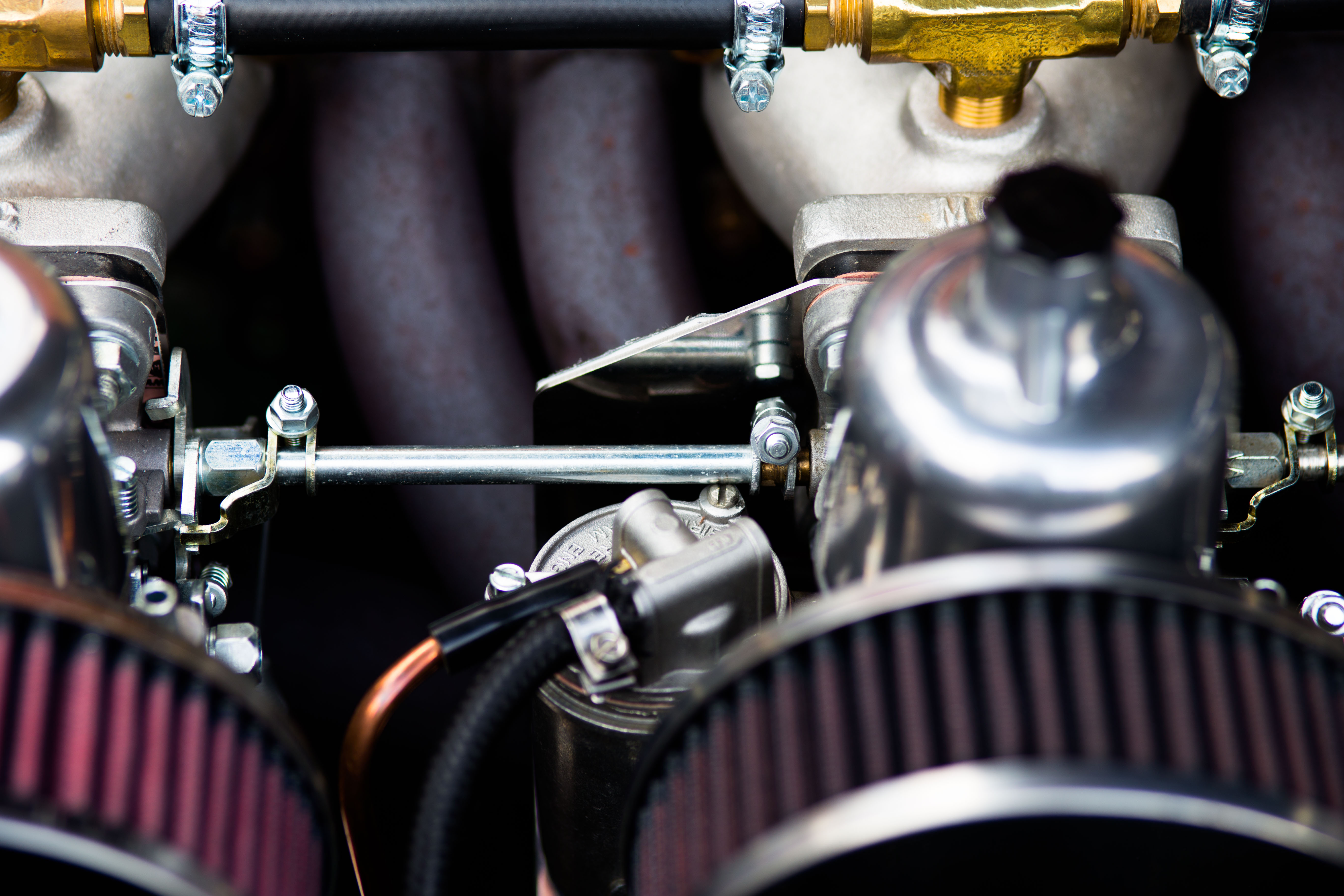
Connecting the front carb also taxed the mind. Gary recommends drilling a hole in the left hand side of the middle carb butterfly spindle and then another hole to put a split pin thru to hold a narrowed down throttle spindle. I could not easily drill a straight hole (if not exactly straight it would not turn) but decided to use clamp to hold a standard length throttle spindle on the end of the butterfly spindle – see photos. The clamp I used was actually in the Throttle spindle kit with the end cut off (the end usually activates the butterfly). I needed to use the smaller screw head on the middle fuel pot and also slightly file down the edge for it to clear fully. The clamp between the copper end of the butterfly spindle and the steel throttle spindle shows clearly in the photo IMG 8930-12


Choke – Gary Herbold and others say that you only need to choke the middle and rear carbs using standard parts. In my experience this is true and it starts fine and runs fine on choke.

Tuning – much easier than the two carb set up as you have 2 cylinders fed just from one carb. Initially I carefully cleaned each carb and made sure they rose and fell perfectly (rear one was sticking and needed jet centring) and then using calipers I set each of the jets to be the same distance down from the bridge so I knew each was equal. Starting the engine, the usual balance of airflow and then tuned each carb using Colortune glass spark plug until blue (slightly richen).


Next photo – The clamp between the copper end of the butterfly spindle on the middle carb and the steel throttle spindle activating the front carb